Post by DeadlyPeace on Jul 11, 2007 13:04:55 GMT -5
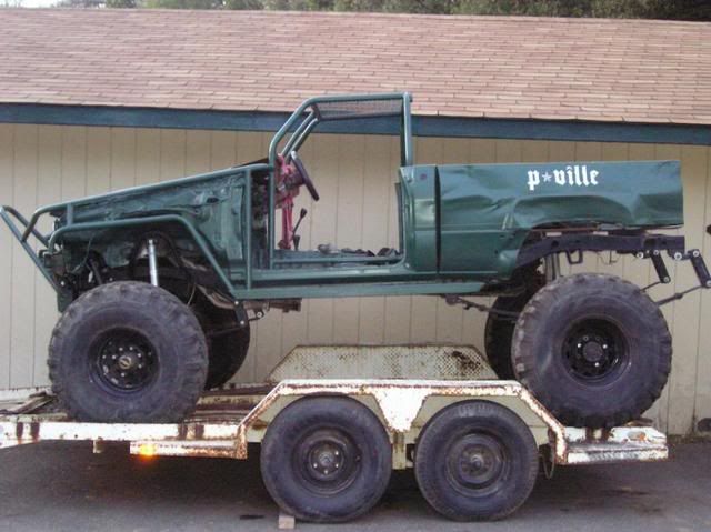
Another TOY has followed me home, but it needed some work. It has a Dana 44 w/ a Detroit locker up front, a welded Dana 60 in the rear, and rolling on 38’s. Formally know as Biff, now named Toyzilla.

The only parts it needed to get it to move under its own power were a T-case output shaft, drivelines, and the pinion flange for the axles. This really made it fun for loading onto the trailer, especially with the flange missing cuz as the pinion would slide down into the pumpkin the axle would lock up. To fix this we used some vise-grips to lightly grip to the pinion to hold it out in the right place and a floor jack to hold the rear wheels off the ground until they needed to roll up onto the trailer. It was quite a workout with just a com-a-long and no ramps.
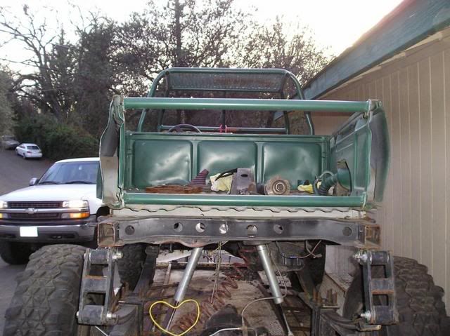
Here are some pics of it after getting it home.

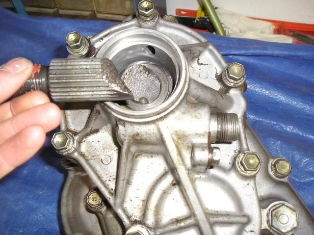
T-case w/ 4.7:1 gears..............Can we say OUCH!!!
Blue welcoming Toyzilla home

Here’s what I’ve done so far. The first thing was to get new seats and a new pinion flange. I had a spare stock T-case that I temporarily used with the bent up front driveline to back it down off the trailer to work on it and move it around. I will eventually get an adapter for making the spare a dual case with an upgrade to a 23 spline input shaft so I will use the input shaft in it to replace the broken one. I also replace most of the bushings and up graded some bolts to a grade 8 and/or larger size.
I removed the cowling and dash that they made and cleaned up some of the unwanted wiring. Then started on making a new dash and cowling.
Figuring out the basic shape I wanted for the dash.
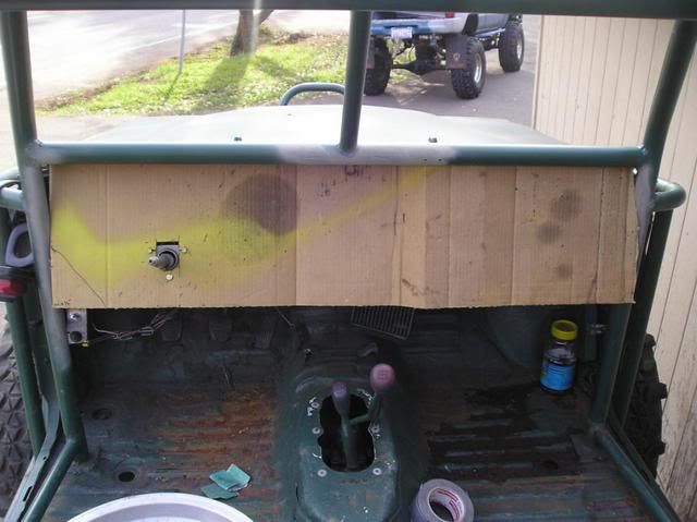
The basic shape of the dash put into metal form
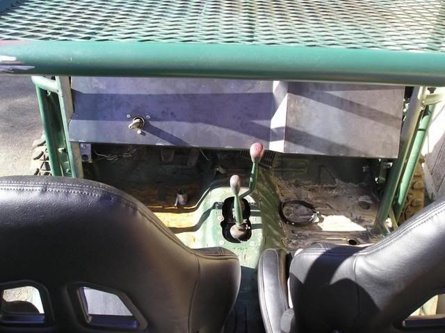
Starting to form the sides of the dash
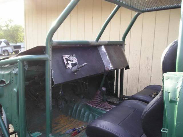

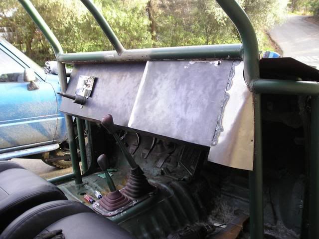
Sides of dash finished.
I removed the levers from the steering column cluster and cut and grinded all the excess off so they wouldn’t stick out. To cover the column I will be using 2-21/2 inch exhaust pipe with one end expanded out to fit the inside of the column boot.
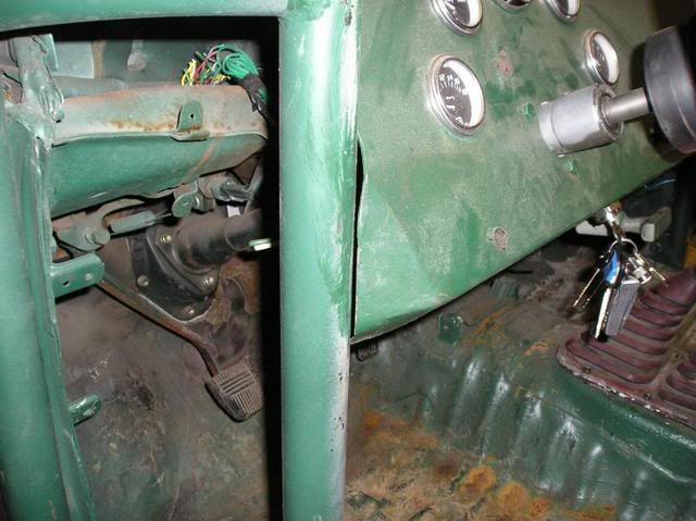

New cowling in the making.
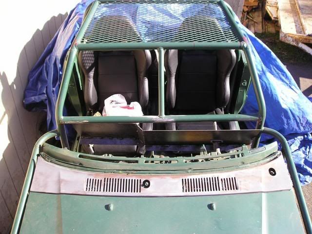
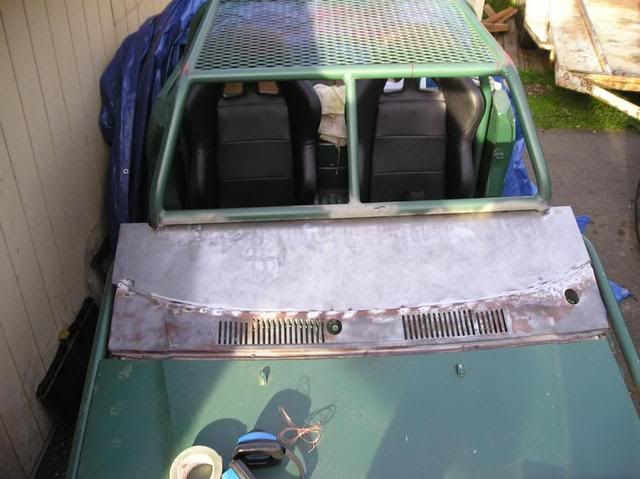
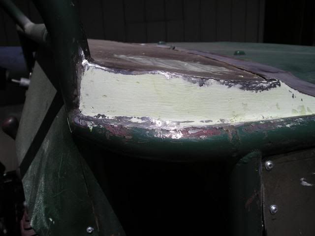
For the side of the cowling I shaped it to the curve of the tubing with an extra 1/2 inch that was bent over to make a smooth rounded edge. Then I shaped a piece of sheet metal to go under the lip and down to the tubing. After welding it into place I bondoed the side for smoothness so it didn’t have a recessed area.

New Gauges

Switches for the headlights, reverse lights, rock lights, and future dome light and e-fan. To the bottom left of the pic is the ignition switch.

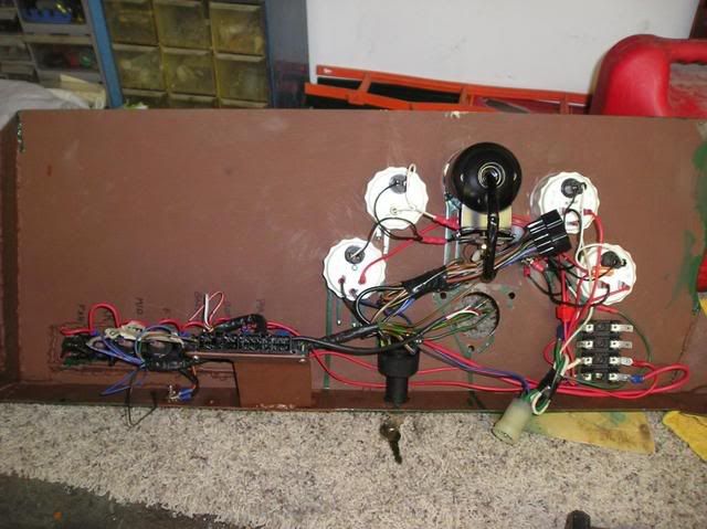
I made the dash so that it was removable so it would be easier for adding future items or fixes. So here I made all the wiring so it was all attached to the back of the dash and in order to remove it I just need to unplug two stock wire connecters from the back. From the front I have one screw at the top and one on the side end (both on the right side); then the three bolts that hold the steering column in place. (Future items so far are a stereo, CB, cup holder, and maybe a small glove box).
To help make the outside looking better I added some sheet metal panels to hide the inner fender area. I also made the panels removable for easy access for running wires or whatever behind them. I also plan on adding on tube half doors so I’ll need to get to the hinge bolts too if I use the stock mounts.
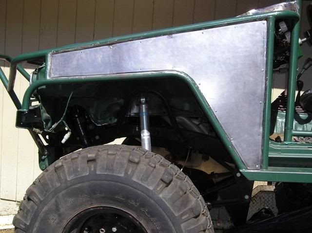
Unfortunately whoever did the tubing before didn’t try to make both sides the same. The left side was about an inch wider between the upper and lower tubes at the front end.
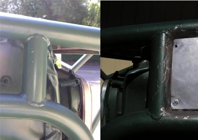
Here I cut off and cleaned up the front support tube. I also cut an inch off the end of the lower tube and welded it back on to the bumper.
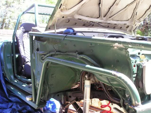
The lower tube was also in about two inches futher in then the left side so I used a frame-straightening jack to push it into place.

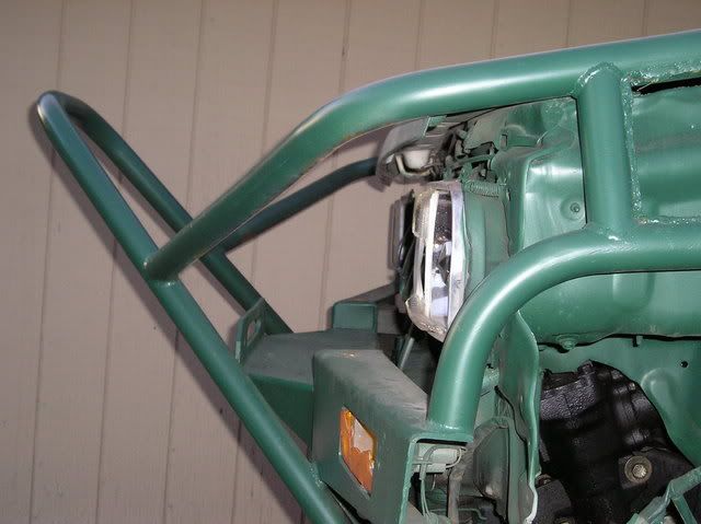
I then cut and welded a new support tube into place. On the upper tube you can see one of the plates I welded on for screwing on the side panel.

Right side panel.
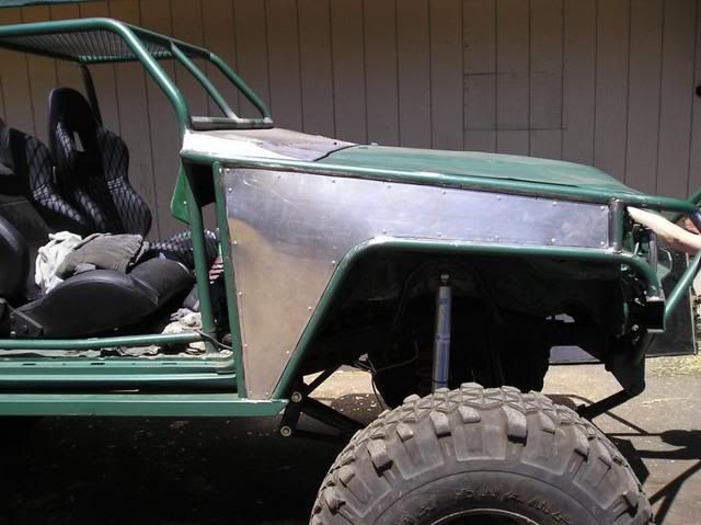
After replacing the input shaft in the T-case and making new drivelines, I took Zilla for a small test drive to see how it handled. It did really well, but after a while I started to notice a creaking sound every time I made a wide turn. Come to find out that the frame was cracked on the left side were the side frame rail runs into the front coss member. The crack in the next pic I believe happened during the test drive.
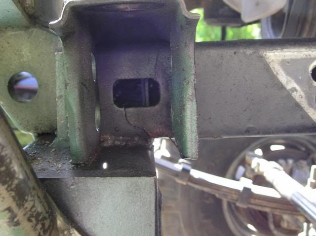
But looking closer at the frame I noticed that, as you can see from the pic, at some point the lower and inside part of the frame were completely crack and badly welded back together and cracked apart again. This would be a good reason for checking out a vehicle real well before buying it. I knew I would come across a few small things that would need fixing cuz I didn’t look real close before buying it. Something like this I didn’t expect, but for the price I talked the guy down to I couldn’t pass it up, and still would have bought it if I knew about this.
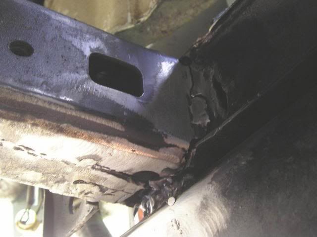
To fix this problem I cleaned up the old welds to the frame and re-welded it correctly. I also cut a 1/4 inch section from the back half of the body mount for welding a 1/4 inch angle iron to fit into. Then re-welded the body mount to it.
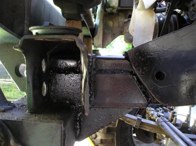
I then made some gussets for extra support. I used 1/4 inch thick for the bottom one and 3/8 inch thick for the two side ones. This should do it, but with 38’s, and maybe at some point larger tires, I wanted to be sure it would be enough. So I made a cross member at the P/S pump also.

For the cross member I used a 1/4 inch plate and drilled bolt holes so it would use the bottom two bolts from the P/S pump, which I also increased the size of. I then welded a 1/4x2x2 inch tube steel onto the plate so that the corners of the tube steel would be going front to back and top to bottom. This way it would cover more of the frame width and keeping the strength in the middle of the cross member where I needed to notch it for the engine pulleys.

Marking the other side.
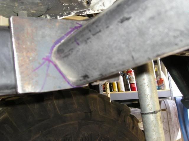
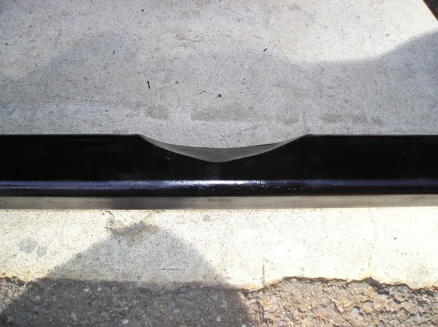
Before I was able to mark the other side, as I mentioned above I had to make a notch in the top of the cross member for the engine pulleys. I gave them about a 1/2 inch of clearance from the larger pulley so I have room for removing and putting on the belts when needed without having to remove the cross member.
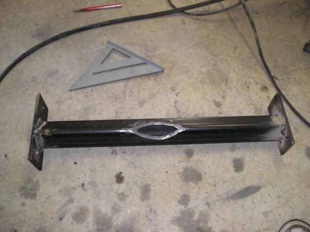
Here’s the finished cross member. To keep dirt, water, and what have you from getting inside I welded a piece of 1/16 inch thick sheet metal over the hole at the notch.

Here’s a side view of the notch for the pulleys.
Now that the cross member was complete I needed to re-route my lower radiator hose. To do this I took the existing rubber hose from the radiator and turned it so it went up instead off to the side. I then removed the metal line and had a new one bent up out of 1 1/4 inch exhaust tubing. It was basically the same shape as the original one, but with two 45* bends on the lower end to bring the end up to the new location of the rubber hose. It was also about 2 inches longer at each end. After getting the hoses all hooked up I made up some mounts to hold it into place.
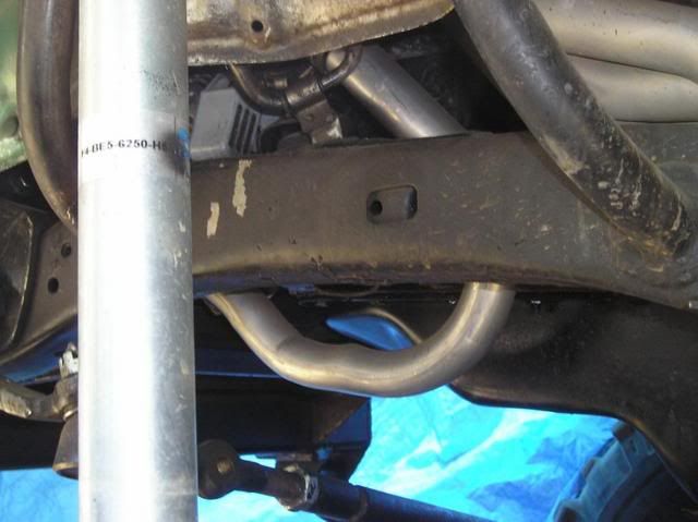
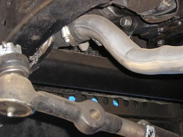
Here’s how it looks right now.
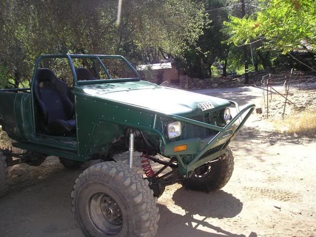
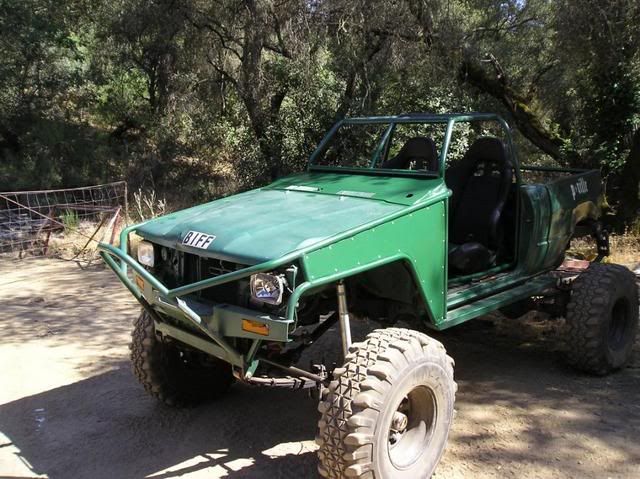
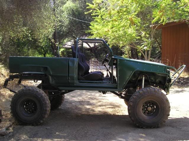
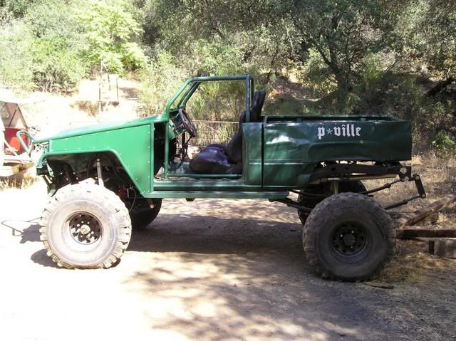
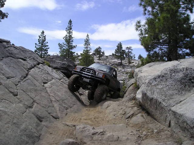
Here’s some pics on one of the test runs on a hill in back of the house.


Future mods and/or ideas to date are:
[/li][li] Removable cargo box(?)
[/li][li] Removable(?) cage for the flatbed
[/li][li] Chevy alternator
[/li][li] Hinged buggy springs or Link setup in rear
[/li][li] ARB locker for front axle
[/li][li] Diff skid plates
[/li][li] Removable plexiglass windshield
[/li][li] Removable canvas top and doors (for winter and hot summer trips)
[/li][li]A lighter green paint job with scales in it
[/li][li] Maybe someday larger tires (up to 44’s)
[/li][li] Lifting seats up for better view over the front end.
[/li][li] Redoing the cab cage for more headroom (after lifting seats)
[/li][/ul]
[/color]

The only parts it needed to get it to move under its own power were a T-case output shaft, drivelines, and the pinion flange for the axles. This really made it fun for loading onto the trailer, especially with the flange missing cuz as the pinion would slide down into the pumpkin the axle would lock up. To fix this we used some vise-grips to lightly grip to the pinion to hold it out in the right place and a floor jack to hold the rear wheels off the ground until they needed to roll up onto the trailer. It was quite a workout with just a com-a-long and no ramps.
Here are some pics of it after getting it home.


T-case w/ 4.7:1 gears..............Can we say OUCH!!!

Blue welcoming Toyzilla home

Here’s what I’ve done so far. The first thing was to get new seats and a new pinion flange. I had a spare stock T-case that I temporarily used with the bent up front driveline to back it down off the trailer to work on it and move it around. I will eventually get an adapter for making the spare a dual case with an upgrade to a 23 spline input shaft so I will use the input shaft in it to replace the broken one. I also replace most of the bushings and up graded some bolts to a grade 8 and/or larger size.
I removed the cowling and dash that they made and cleaned up some of the unwanted wiring. Then started on making a new dash and cowling.
Figuring out the basic shape I wanted for the dash.

The basic shape of the dash put into metal form

Starting to form the sides of the dash


Sides of dash finished.
I removed the levers from the steering column cluster and cut and grinded all the excess off so they wouldn’t stick out. To cover the column I will be using 2-21/2 inch exhaust pipe with one end expanded out to fit the inside of the column boot.


New cowling in the making.


For the side of the cowling I shaped it to the curve of the tubing with an extra 1/2 inch that was bent over to make a smooth rounded edge. Then I shaped a piece of sheet metal to go under the lip and down to the tubing. After welding it into place I bondoed the side for smoothness so it didn’t have a recessed area.


New Gauges

Switches for the headlights, reverse lights, rock lights, and future dome light and e-fan. To the bottom left of the pic is the ignition switch.

I made the dash so that it was removable so it would be easier for adding future items or fixes. So here I made all the wiring so it was all attached to the back of the dash and in order to remove it I just need to unplug two stock wire connecters from the back. From the front I have one screw at the top and one on the side end (both on the right side); then the three bolts that hold the steering column in place. (Future items so far are a stereo, CB, cup holder, and maybe a small glove box).

To help make the outside looking better I added some sheet metal panels to hide the inner fender area. I also made the panels removable for easy access for running wires or whatever behind them. I also plan on adding on tube half doors so I’ll need to get to the hinge bolts too if I use the stock mounts.

Unfortunately whoever did the tubing before didn’t try to make both sides the same. The left side was about an inch wider between the upper and lower tubes at the front end.

Here I cut off and cleaned up the front support tube. I also cut an inch off the end of the lower tube and welded it back on to the bumper.

The lower tube was also in about two inches futher in then the left side so I used a frame-straightening jack to push it into place.

I then cut and welded a new support tube into place. On the upper tube you can see one of the plates I welded on for screwing on the side panel.

Right side panel.

After replacing the input shaft in the T-case and making new drivelines, I took Zilla for a small test drive to see how it handled. It did really well, but after a while I started to notice a creaking sound every time I made a wide turn. Come to find out that the frame was cracked on the left side were the side frame rail runs into the front coss member. The crack in the next pic I believe happened during the test drive.

But looking closer at the frame I noticed that, as you can see from the pic, at some point the lower and inside part of the frame were completely crack and badly welded back together and cracked apart again. This would be a good reason for checking out a vehicle real well before buying it. I knew I would come across a few small things that would need fixing cuz I didn’t look real close before buying it. Something like this I didn’t expect, but for the price I talked the guy down to I couldn’t pass it up, and still would have bought it if I knew about this.

To fix this problem I cleaned up the old welds to the frame and re-welded it correctly. I also cut a 1/4 inch section from the back half of the body mount for welding a 1/4 inch angle iron to fit into. Then re-welded the body mount to it.

I then made some gussets for extra support. I used 1/4 inch thick for the bottom one and 3/8 inch thick for the two side ones. This should do it, but with 38’s, and maybe at some point larger tires, I wanted to be sure it would be enough. So I made a cross member at the P/S pump also.

For the cross member I used a 1/4 inch plate and drilled bolt holes so it would use the bottom two bolts from the P/S pump, which I also increased the size of. I then welded a 1/4x2x2 inch tube steel onto the plate so that the corners of the tube steel would be going front to back and top to bottom. This way it would cover more of the frame width and keeping the strength in the middle of the cross member where I needed to notch it for the engine pulleys.

Marking the other side.

Before I was able to mark the other side, as I mentioned above I had to make a notch in the top of the cross member for the engine pulleys. I gave them about a 1/2 inch of clearance from the larger pulley so I have room for removing and putting on the belts when needed without having to remove the cross member.

Here’s the finished cross member. To keep dirt, water, and what have you from getting inside I welded a piece of 1/16 inch thick sheet metal over the hole at the notch.

Here’s a side view of the notch for the pulleys.

Now that the cross member was complete I needed to re-route my lower radiator hose. To do this I took the existing rubber hose from the radiator and turned it so it went up instead off to the side. I then removed the metal line and had a new one bent up out of 1 1/4 inch exhaust tubing. It was basically the same shape as the original one, but with two 45* bends on the lower end to bring the end up to the new location of the rubber hose. It was also about 2 inches longer at each end. After getting the hoses all hooked up I made up some mounts to hold it into place.


Here’s how it looks right now.


Here’s some pics on one of the test runs on a hill in back of the house.


Future mods and/or ideas to date are:
- Custom flatbed with custom toolbox underneath
[/li][li] Removable cargo box(?)
[/li][li] Removable(?) cage for the flatbed
[/li][li] Chevy alternator
[/li][li] Hinged buggy springs or Link setup in rear
[/li][li] ARB locker for front axle
[/li][li] Diff skid plates
[/li][li] Removable plexiglass windshield
[/li][li] Removable canvas top and doors (for winter and hot summer trips)
[/li][li]
[/li][li] Maybe someday larger tires (up to 44’s)
[/li][li] Lifting seats up for better view over the front end.
[/li][li] Redoing the cab cage for more headroom (after lifting seats)
[/li][/ul]
[/color]


 [/glow]


 Nice job bro! That is one hell of a beast you found.




 For the lights, and I dont know if this would work, but you could buy some aftermarkets and stick em off the top like crab eyes. I dont know if it would limit visibilty etc.